Precision Core Sleeves With Controlled ID and OD
Precision core sleeves manufactured for injection molds where internal and external cylindrical surfaces must remain concentric, stable, and accurately fitted.
Project Background
Project Background
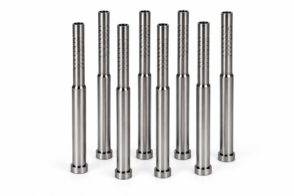
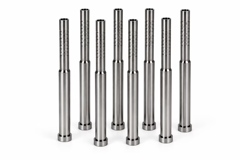
This case focuses on precision core sleeves used for guiding, locating, supporting, or forming cylindrical mold features. The image shows a group of similar sleeve components where consistent geometry and controlled ID/OD relationship are important.
For core sleeves, checking the inner diameter and outer diameter separately is not enough. The two cylindrical surfaces must be aligned to the same functional centerline. If the ID and OD are off-center, the sleeve may still pass individual size checks but create assembly misalignment, uneven wear, or unstable molded features.
Engineering Challenges
Engineering Challenges
ID/OD concentricity
The inner bore and outside diameter must be controlled as one functional relationship.
Cylindrical accuracy
Roundness, straightness, and cylindricity affect fit and movement inside the mold.
Multi-piece consistency
When multiple sleeves are used in one mold set, dimensions must remain consistent across the batch.
Surface stability
Ground and polished surfaces must support fitting, sliding, or forming requirements without rough contact.
Engineering Solution
Engineering Solution
Drawing Review
MOLDVANCE manufactures precision core sleeves by controlling the cylindrical datum relationship throughout machining and inspection. The process focuses on keeping ID, OD, shoulder areas, and working length aligned...
Process Planning
CNC turning is used for the main sleeve geometry, followed by precision grinding for critical cylindrical surfaces. Polishing is applied where sliding or forming surfaces require smoother contact.
Manufacturing Route
Manufacturing Route
Machine the sleeve body, shoulders, end faces, and main cylindrical profile.
Control the bore according to the required mating core or locating feature.
Finish OD, fitting surfaces, and cylindrical reference areas.
Improve contact surfaces where smoother sliding or release is needed.
Check concentricity, length, shoulder position, and key reference dimensions.
Compare critical dimensions between multiple sleeves in the same production set.
Material and Requirements
Material and Requirements
Materials
Material follows the customer drawing and mold application requirement. For precision core sleeves, material choice should consider dimensional stability, wear resistance, grinding performance, and compatibility with mating mold components.
Heat Treatment
Heat treatment depends on the drawing and material condition. When heat treatment is required, machining allowance and post-treatment grinding are planned to maintain concentricity and cylindrical accuracy.
Surface Requirement
Fitting surfaces require controlled grinding quality. Internal and external working surfaces are finished according to the mold’s assembly, guiding, or forming requirement.
Precision Control
Precision Control
Tolerance Capability
Tolerance requirements are reviewed based on sleeve length, wall thickness, bore size, and inspection method. Critical features can be controlled tightly where the sleeve design and process allow
Key Control Points
- Internal diameter
- Outside diameter
- ID/OD concentricity
- Cylindricity
| Critical Feature | Why It Matters |
|---|---|
| Internal diameter | Controls mating with core pins, cores, or locating parts. |
| Outside diameter | Controls fit in the mold plate or sleeve housing. |
| ID/OD concentricity | Prevents misalignment between mating components. |
| Cylindricity | Supports stable fit and movement. |
| Shoulder position | Affects assembly height and location. |
| Working length | Controls functional position inside the mold. |
Quality Inspection
Quality Inspection
Inspection Method
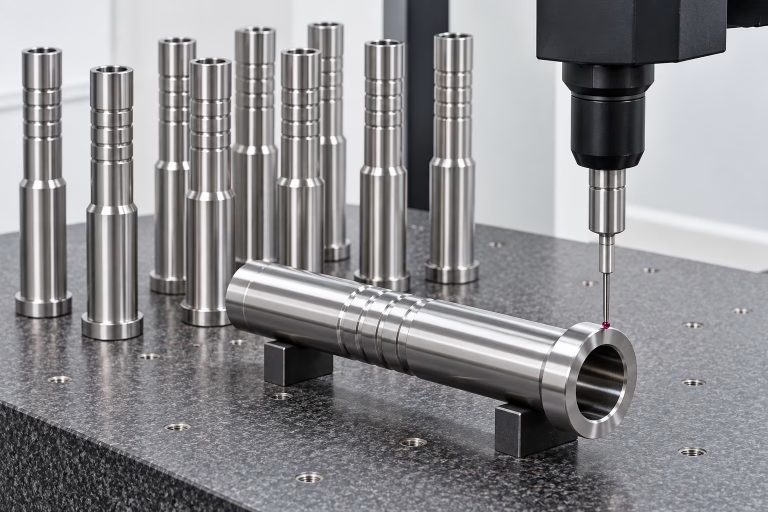
Inspection can include CMM measurement, bore gauge inspection, micrometer checks, roundness/concentricity checks, and comparison of critical dimensions across the same production set.
RFQ CTA
Need Similar Precision Components?
Send your drawings, material requirements, quantity and inspection expectations for engineering review.